Can the tool reach the feature?
Deep pockets, narrow slots, undercuts and small internal corners need early attention. Identify which shapes are functional and which could be adjusted.

For housings, mounting brackets, plates and shaped components. Define the pockets, surfaces and relationships that make your part work in its assembly.
Start with the geometry
The appropriate machining route depends on access to the features, workholding and the requirements across each face.
Deep pockets, narrow slots, undercuts and small internal corners need early attention. Identify which shapes are functional and which could be adjusted.
Thin walls, slender sections and extensive material removal can affect the machining strategy. Share the intended use and any flatness requirements.
Hole patterns and features on different faces may need a common reference. Use drawing datums and clearly defined positional requirements.
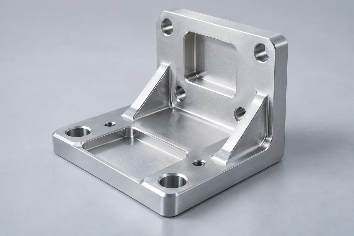
Example / Mounting bracket
For a mounting bracket, the base face and hole pattern may be more important than the outer profile. The brief should make that hierarchy visible.
This is an illustrative part study, not a record of a completed customer project.
What to put on the drawing
| Feature | Useful drawing detail |
|---|---|
| Pockets and slots | Depth, internal corner radii and any critical wall thickness. |
| Threads | Thread designation, class where required, usable thread depth and location. |
| Mating surfaces | Relevant datum references, flatness, roughness and coating exclusions. |
| Appearance | Visible faces, allowed tool marks, finish reference and color expectations. |
| Edges | Required chamfers, edge breaks and any edge that must remain sharp. |
Complete the specification
A finish can affect fit or appearance. Discuss it alongside the geometry, and identify dimensions that apply after finishing.
Start with the required properties and exact grade. If alternatives are acceptable, describe what must remain unchanged.
Material & finish guideTell us which dimensions are critical, what records you need and whether an approval sample is part of the order.
Inspection workflowThat depends on the geometry, tool access and relationships between features. Share the complete model and drawing. A machining route should be selected after those requirements are reviewed, rather than from the part appearance alone.
A rotating milling tool naturally leaves a radius in an internal corner. If a square internal corner is functionally necessary, flag it so an alternative geometry or additional process can be discussed.
Identify the visible faces and give a finish reference or written acceptance criteria. Specify whether tool marks, color variation or handling marks are acceptable, and agree on any sample approval before production.
Share your model, drawing and quantity. Highlight the features that matter most.